Sunday, December 6, 2009
How Selective Is Naval Eod
The transistor is a semiconductor electronic device that acts as amplifier, oscillator, switch, or rectifier. The term "transistor" is an English contraction of resistor transfer ("transfer resistance"). Currently they are found in virtually all artifacts everyday household: radios, televisions, tape recorders, audio and video players, microwave ovens, washing machines, automobiles, refrigeration equipment, alarms, quartz watches, computers, calculators, printers, fluorescent lamps, X-ray machines, scanners , ultrasound, mp3 players, cell phones, etc..
transistor types
Transistor contact tip
the first transistor was obtained gain invented in 1947 by J. Bardeen and W. Brattain. It consists of a germanium base on which they rest, close together, two metal spikes that form the emitter and collector. The emitter current is able to modulate the resistance "seen" in the collector, hence the name of "transfer resistor." It is based on surface effects, little known in his day. It is difficult to make (the points were adjusted by hand), fragile (one strike could move the ends) and noisy. But he lived with the junction transistor (W. Shockley, 1948) due to greater bandwidth. It has now disappeared.
binding Transistor bipolar
The bipolar junction transistor, or BJT for its acronym in English, is made primarily on a single crystal of germanium, silicon or gallium arsenide, which are qualities of semiconductors, conductive state between as metals and insulators such as diamond. On the glass substrate, are contaminated in a very controlled three zones, two of which are the same type, NPN or PNP, leaving two junctions formed NP.
N zone with elements donor of electrons (negative charges) and the P side to accept or "holes" (positive charges). Normally used as acceptors P elements to Indio (In), aluminum (Al) or gallium (Ga) and donors N to Arsenic (As) or phosphorus (P).
PN junction configuration, result in PNP or NPN transistor, where the middle letter always corresponds to the characteristic of the base, and two to the emitter and collector, while are the same type and opposite to the base, have different contamination between them (typically, the issuer is much more polluted than the collector).
The mechanism that represents the behavior semiconductor depend on such contamination, the associated geometry and the type of technology of pollution (gaseous diffusion, epitaxial, etc.) and the quantum behavior of the union.
Unijunction Transistor
also called junction field effect (JFET), was the first field effect transistor in practice. The material forms a bar-type silicon semiconductor N or P. At the end of the bar provides an ohmic contact, we have thus a field effect transistor type N of the form more basic. If P two regions are distributed in a bar of N material and connected externally to each other, there will be a door. One of these contacts will call another supplier and drain. Applying a positive voltage between the drain and the pump and connecting door to the supplier, establish a current, which call drain current with zero bias. With a potential negative gate voltage which we call a bottleneck, ceases conduction in the channel.
Field Effect Transistor
The field-effect transistor, or FET for its acronym in English, which controls the current versus voltage, have high input impedance.
field effect transistor junction, JFET, built by a PN junction.
Field Effect Transistor Insulated Gate, IGFET, in which the gate is insulated by a dielectric channel.
Field Effect Transistor MOS, MOSFET, which means MOS Metal-Oxide-Semiconductor, in this case the gate is metal and is semiconductor channel separated by an oxide layer.
Phototransistor
The phototransistors are sensitive to electromagnetic radiation at frequencies near that of light.
Homeopathy Treat Lipoma
LIGHT EMITTING DIODE TRANSISTOR


O also known as LED (Light-Emitting Diode) is a semiconductor device (diode) that emits incoherent narrow-spectrum light when directly biased PN junction of it and he runs an electric current. This phenomenon is a form of electroluminescence. The color (wavelength) depends on the semiconductor material used in the construction of the diode and can range from ultraviolet through the visible to infrared. Light emitting diodes that emit ultraviolet light also are called LED UV (UltraViolet Light-Emitting Diode) and those that emit infrared light typically receive the designation of IRED (Infra-Red Emitting Diode). Were invented by Oleg Losev.
Physical performance is that, in semiconductors, an electron moving from the conduction band to the valence, loses power, this energy loss can manifest in the form of a photon off, with an amplitude, an address and a random phase. The one that lost energy when it passes an electron from the conduction band to the valence is manifested as a photon detached or another form of energy (heat for example) will depend primarily the type of semiconductor material.
When a semiconductor diode is forward biased, the holes in the p zone move to the area n and n electrons of the area to the area p, both loads are the displacement current through the diode. If electrons and holes are in the same region, can recombine, ie, electrons can move to "fill" gaps, "falling" from a higher energy level to a lower more stable. This process emits a photon often in direct band gap semiconductor with the energy corresponding to its band gap.
Advantages:
Technology LED lighting is a durable, low-power, low voltage, flexible and environmentally friendly. It is a fixture which by its nature is called solid light. See Chapter 8.
In 1990 he made the first blue LED. This allowed white LED manufacturing. With this relatively recent development system outperformed as LED light source further and future projection.
Currently all major lighting manufacturers are betting on this technology will be the main light source of the future. Each year there are LEDs on the market better, more efficient, bright, safe, comfortable to use and parallel to wider use, more economical. Experts estimate that by 2012 the LED will light fixture with greater market power.
Saturday, December 5, 2009
Talbotsprice Adjustment Policy
The Counter


L A OPTO ELECTRONICS
those are called optoelectronic devices that combine optics and electronics to work.
An example of this may be a remote control device or crepuscular.
generally optoelectóronicos components are those capable of converting light into electrical energy or vice versa.
are divided into two groups:
Photosensitive : From light excitation or control changes produce electricity.
These components are the LDR, fotopilas, fototiristores, fotoleds, diodes and bipolar transistors.
Electro luminescent : Based on the excitation by an electric current in those causing the emission of light energy in the form of visible radiation or not.
are components electro luminescent LEDs (Light Emitting Diode) and all your settings, infrared emitting diodes IRED (Infrared Emitting Diode) Diode Laser (Light Amplification by Simulate Emission of Radiation), which produce stimulated emission of photons as a monochromatic radiation and liquid crystal displays LCD (Liquid Crystal Display).
VARIABLE RESISTANCE WITH LIGHT
A LDR is an optoelectronic device capable of varying its resistance according to
light falling on it.
Cuanta más luz recibe, más baja es la resistencia.
En un LDR se han de tener en cuenta varias cosas:
*En 1er lugar, la amplitud de resistencias. Sin luz, una buena LDR se ha de comportar como un circuito abierto. Y su mínima resistencia ha de ser lo más pequeña posible, en torno a los cien ohmios, o menos si pudiera ser.
* En segundo lugar, se ha de tener en cuenta, el tiempo que emplea una LDR en pasar de un estado de máxima resistance to one of least resistance, that is, what it takes to switch from a position of circuit "closed" to a state of "open" circuit.
This time should be as small as possible, and has to be about the second.


Thursday, December 3, 2009
Gretchen Rossi In Blue And White Monokini
THE LDR variation of light-activated
acontinuación This project will explain what do my work group, and of course me too, well this project is done to perceive and count as in this case a car passes:

acontinuación This project will explain what do my work group, and of course me too, well this project is done to perceive and count as in this case a car passes:
This is the circuit:
Click to view more closely
circuit elements first:
- LDR: optoelectronic device is able to vary their resistance according to light falling on it.
- Resistance
- Transistor
- Light Emitting Diode
- Compuerta logic NAND
- Potentiometer
- Condenser
- Chip integrated 4518
- 2749 Integrated Chip
Tuesday, September 8, 2009
Medication Stomach Flu
THE SAD SONG BIRD

 At a time more or least 10 years ago in a small town in the Peruvian Andes in a dark forest full of ice and deep darkness, gloom and living spaces a inseparable friends and adventurers, these friends were called Luis and Jorge. Luis was a young adventurer, a young George a little apprehensive.
The beauty of this action is that the bird was reunited with his flock, and bad for me is that I can not hear the melody that although sadness overwhelms you loved me listen and it's always good to face the sadness even more if you're alone, it's good to get thinking about life, that of how it affects you and yours to others. You'll think I'm crazy, that there can be such a majestic bird, but I know it's true, I know it exists and that in a corner of this world so wild and not the means to meet.


 At a time more or least 10 years ago in a small town in the Peruvian Andes in a dark forest full of ice and deep darkness, gloom and living spaces a inseparable friends and adventurers, these friends were called Luis and Jorge. Luis was a young adventurer, a young George a little apprehensive.
 In this forest used to go nocturnal creatures foreign to them.  These creatures out at night and began to rule his land in the dark skies and singing a song to listen felt strange sensations of pain, sadness and regret, perhaps through the sound transmitted to us their feelings and perhaps were unhappy at not being able to show the world, only to emerge at nightfall, and where they were protected by the vast darkness of the ignorant and disturbed night hunters, where our young players regretted having belonged to them, and Jorge Luis and some friends decided on a night hunt, and I think that was the dumbest
  they did in your life, but I do not think, it was they were afraid, especially Luis, but still set off an abandoned house where they lived, even with the fear that had managed to catch one, could not believe it had a strange kind but the moment of happiness was short-lived as we realized it was a very beautiful bird, the bird began to sing and gave us a strange sense of solitude and captivity, we are so impressed we decided to release this majestic bird of the night.
These creatures out at night and began to rule his land in the dark skies and singing a song to listen felt strange sensations of pain, sadness and regret, perhaps through the sound transmitted to us their feelings and perhaps were unhappy at not being able to show the world, only to emerge at nightfall, and where they were protected by the vast darkness of the ignorant and disturbed night hunters, where our young players regretted having belonged to them, and Jorge Luis and some friends decided on a night hunt, and I think that was the dumbest  they did in your life, but I do not think, it was they were afraid, especially Luis, but still set off an abandoned house where they lived, even with the fear that had managed to catch one, could not believe it had a strange kind but the moment of happiness was short-lived as we realized it was a very beautiful bird, the bird began to sing and gave us a strange sense of solitude and captivity, we are so impressed we decided to release this majestic bird of the night.
The beauty of this action is that the bird was reunited with his flock, and bad for me is that I can not hear the melody that although sadness overwhelms you loved me listen and it's always good to face the sadness even more if you're alone, it's good to get thinking about life, that of how it affects you and yours to others. You'll think I'm crazy, that there can be such a majestic bird, but I know it's true, I know it exists and that in a corner of this world so wild and not the means to meet.
Tuesday, June 16, 2009
Toothpick Bridge Template
... Measuring the speed radar.
After much time I open the blog again to start a new project ...
 A sensor detects the passage of the object and stores a time constant, passing through the second sensor keeps a second time constant to measure the time it takes to pass between the two sensors, subtracts the time of the first sensor while the second sensor.
Then follow the data to convert to Km / h.
sharp 2D120X
The sharp 2d120X analog sensor is a distance, has an analog value in relation to the object distance, the greater the distance less stress and vice versa.


# include # define route 50
radar 13 # define MAX 50 # define
Tiemposensor1 unsigned long int, Tiemposensor2 / / declare variables int long
RealTime;
int x, x2;
int distance = 400;
sensor1 int = 0;
sensor2 int = 1;
float speed;
LiquidCrystal
lcd (12, 11, 10, 5, 4, 3, 2); / / are chosen to control the LCD pin
void setup () {
Serial.begin (9600) / / 9600 baud transmission rate
pinMode (sensor1, INPUT) / / sensor 1 and 2 as inputs.
pinMode (sensor2, INPUT);
pinMode (radar, OUTPUT) / / Output radar
} void loop () {x = analogRead
(Sensor1) / / read the sensor 1 until the distance is less than the selected
do {x = analogRead (sensor1)
} while (x < tiemposensor1 =" millis();" x2 ="analogRead" x2 =" analogRead" tiemposensor2 =" millis();" tiemporeal =" (Tiemposensor2" velocidad =" ((0.1" velocidad =" espacio/"> MAX) {/ / if the speed is greater than the maximum speed
predefined digitalWrite (radar, HIGH) / / active radar
the delay (200);
digitalWrite (radar, LOW);
Serial.print ("Excessive speed ... RADAR ON") / / message on the Serial.println
PC screen (speed);
lcd.clear ();
lcd.home ();
lcd.print (ON RADAR !!!"); / / message on the LCD
delay (500) ;
}}


After much time I open the blog again to start a new project ...
designed circuit is capable of measuring the velocity of an object passing between two sensors, the "heart" of the circuit is the Arduino system, which is a section on this page.
This radar is capable of measuring speeds between 0 and 500km / h, once it detects the speed displayed on a backlit LCD screen, send a message to the PC and if the measured speed exceeds the specified will activate a camera and displays a message on both screens (PC and LCD).
 A sensor detects the passage of the object and stores a time constant, passing through the second sensor keeps a second time constant to measure the time it takes to pass between the two sensors, subtracts the time of the first sensor while the second sensor.
 Then follow the data to convert to Km / h.
! Sensors are 10 cm away!
Parts list
· Arduino Duemilanove.
· LCD display hitachi blue 44780. 16x2.
· Sensors sharp 2D120X
· 4.7 K potentiometer
· Serve Futaba S3003
alpha * Software Arduino 0013. Sensor
Parts list
· Arduino Duemilanove.
· LCD display hitachi blue 44780. 16x2.
· Sensors sharp 2D120X
· 4.7 K potentiometer
· Serve Futaba S3003
alpha * Software Arduino 0013. Sensor
sharp 2D120X
The sharp 2d120X analog sensor is a distance, has an analog value in relation to the object distance, the greater the distance less stress and vice versa.
can see their data sheet on this page:
http://www.datasheetcatalog.org/datasheets/480/87977_DS.pdf
http://www.datasheetcatalog.org/datasheets/480/87977_DS.pdf
The function of the servo, is none other than pressing the button shutter of the camera ... (not available for PC-controlled camera, or with remote trigger.) The servo makes a little money at the time of activation of the "radar" you press the shutter button.
to activate the radar also activates the exit 13 of the arduino where we can connect a trigger "more professional" for example a camera or flash.
to handle any cargo from the arduino need to use a relay to do so assemble this circuit:
The complete circuit has been mounted as follows:
The code rduino program is as follows:
# include # define route 50
radar 13 # define MAX 50 # define
Tiemposensor1 unsigned long int, Tiemposensor2 / / declare variables int long
RealTime;
int x, x2;
int distance = 400;
sensor1 int = 0;
sensor2 int = 1;
float speed;
LiquidCrystal
lcd (12, 11, 10, 5, 4, 3, 2); / / are chosen to control the LCD pin
void setup () {
Serial.begin (9600) / / 9600 baud transmission rate
pinMode (sensor1, INPUT) / / sensor 1 and 2 as inputs.
pinMode (sensor2, INPUT);
pinMode (radar, OUTPUT) / / Output radar
} void loop () {x = analogRead
(Sensor1) / / read the sensor 1 until the distance is less than the selected
do {x = analogRead (sensor1)
} while (x < tiemposensor1 =" millis();" x2 ="analogRead" x2 =" analogRead" tiemposensor2 =" millis();" tiemporeal =" (Tiemposensor2" velocidad =" ((0.1" velocidad =" espacio/"> MAX) {/ / if the speed is greater than the maximum speed
predefined digitalWrite (radar, HIGH) / / active radar
the delay (200);
digitalWrite (radar, LOW);
Serial.print ("Excessive speed ... RADAR ON") / / message on the Serial.println
PC screen (speed);
lcd.clear ();
lcd.home ();
lcd.print (ON RADAR !!!"); / / message on the LCD
delay (500) ;
}}
example of an image taken by the "radar" with a model:
collaborated in this project to David Alfaro Muñoz.
Sunday, April 5, 2009
Where Can I Buy Elite Resistance Bands

rhythm lights
3 channel
audio signal is picked up by the microphone which is powered by a 1.8 kΩ resistor. The capacitor of 100 nF decoupling is responsible for letting the continuous RF signal only. The first operational amplifier (A1) is responsible for the initial pre-amplification signal whose gain (sensitivity) is adjusted using potentiometer 1 MW positioned as feedback controller. A second amplifier stage (A2) is responsible for raising a little more level audio signal for delivery to the last amplifier stage (A3) which is arranged as a voltage follower to present a high input impedance and low output impedance, this well prepared for the next three filters do not interact with each other causing malfunction.
If you want to enter the audio signal directly from a speaker can put together a stage of isolation and impedance matching.
In this case the audio signal, either directly from a speaker, go to a knob that can adjust the sensitivity. The transformer used is a common one used in the output stage transistor radios as Spica. In its high-impedance winding (Hz) signal is input and out the low (Lz) thus producing insulation. Remember that the mass in the system is connected directly to one of the terminals of the grid which means extreme danger in case of making a wrong connection.
Next, the amplified audio signal properly and with proper impedance enters the filter module and electric drive.

The first filter (top) passes only the signals that are lower than 500Hz (woofer) that are amplified by the transistor and trigger the power triac shining lights to the rhythm of the sounds of low frequency.
The second filter (center) passes the signals whose frequency is between the 500Hz and 2.5KHz (mids) that are amplified in the same way as the previous module and also trigger a triac to command the lights.
Finally, the bottom filter is responsible for signals to pass frequencies above 2.5KHz, causing them to glow the lights to the beat of the treble.
All three knobs are arranged in charge of regulating the amount of brightness for each channel lights.
Assembly:
With a cooler can be mounted three triacs, making sure that the terminal fin common to all three components, thus achieving efficient heat dissipation. Under these conditions can be hung up to 1500W of power incandescent lights on each channel. For more power can be put more transistors and triacs in parallel.
have to pay close attention when you arm the system and the common ground that goes from the microphone until the last stage of power triacs, is connected to one pole of the electrical grid so it is possible that if not done properly isolates received electric shocks. A crucial point is the microphone capsule has its negative terminal connected to the metallic coating. If the capsule is not isolated (placing it in a thermos cover shrink-wrapped or in a small plastic box) may be shocked by just touching it.
the marking on the front of the box on each channel can be placed LED diodes of different colors directly across 220V output of each channel. This requires placing each LED current limiting resistor of 22 kΩ. We recommend using high brightness LEDs for optimal viewing. You can also place a power indicator LED in parallel with the output of the power supply, in this case the resistance should be 1 kW. If you are using a flashing LED will be placed in parallel with it a capacitor of 100 nF to prevent the flash produces noise in audio amplifiers or mixer.
Seen from the front, with inscriptions visible and down the connection terminals of the triac are, from left to right: Terminal 1, Terminal 2 and Fire.
Power:
§ v max: 12v dc simple
§ I max: 0.5
Saturday, April 4, 2009
Hip Bursitis How Long To Recover

4 microphone mixer
This circuit is often used in panel discussions or meeting rooms to capture the audio from all partners without the need to give each a microphone. Putting this in the middle of the table captures the audio from each of them through which is formed by four electret capsules with a level control for each individual receipt.
We can say that This circuit consists of a hand of four electret modules, each providing power to the capsule through the resistance of 10 k Ω, DC blocking capacitor through 1 uF and put that sign on the end result AF a potentiometer that serves as a reception setting.
opposite end point becomes mute ground to allow that side of the table while the central point is derived from the final signal output. The 100 k Ω resistors and FET transistor form a summing network and pre-amplified signal something which can be applied without problems in both line input and a microphone channel a console. WIRING
output type must be shielded to prevent the resulting sound is "invaded" by interference or noise.
Another recommendation that is not in the scheme is to place a 100 nF capacitor between + V and PCB mass within the unit.
potentiometers to adjust the sensitivity of each of the microphones. This is useful when one side of the table there are more people than the other or when a person speaks too high compared to others. Food
potentiometers to adjust the sensitivity of each of the microphones. This is useful when one side of the table there are more people than the other or when a person speaks too high compared to others. Food
:
§ V max: simple DC 9V
§ I max: 0.1A
§ V max: simple DC 9V
§ I max: 0.1A
Dc Maplestory Privatye Servers

Audio 2 channel mixer
This circuit combines two channels into one.
Its consumption is extremely low and has the advantage that it can expand the number of entries you wish simply duplicating the input sections. Food
:
§ V max: simple DC 9V
§ I max: 0.1A
This circuit combines two channels into one.
Its consumption is extremely low and has the advantage that it can expand the number of entries you wish simply duplicating the input sections. Food
:
§ V max: simple DC 9V
§ I max: 0.1A
Components:
10 k Ω potentiometer R1 C1 0.1 uF
Q1 2N3819 R2 100 k Ω
C2 0.1 uF
R3 10 k Ω potentiometer
C3 0.1 uF
R4 100 to R5
Ω to 6.8 Ω
Q1 2N3819 R2 100 k Ω
C2 0.1 uF
R3 10 k Ω potentiometer
C3 0.1 uF
R4 100 to R5
Ω to 6.8 Ω
Monday, March 16, 2009
How To Open Router Nat Netgear
Project "EVA" Arduino
is a small rover, like the famous explorer mars "or" phoenix "... of course, considering that I have several million dollars .. .

Eva, who is called the friend of wall-e (the film ), is a rover capable of traveling through sandy soils due to the design of his suspension. At first the suspension was controlled by servos but just do not had the strength to lift about 3 kilos weighing robot, so this suspension was designed:
 Here a video suspension running servos (no weight)
As you can see it is a shaft with two angles of 120 degrees linked to the center of the robot and pulling (tentatively) two elastic rubber . This keeps the robot is quite straight and care of putting all the weight in the center of it as practice mind is balanced alone.
camera has a wireless color and sound on the front, controlled by a servo that provides a vision 180 degrees.
Being a robot "" Mars "" "you have adapted some solar panels that cover almost the entire surface of the same:

To control all the robot will use an Arduino board (there is a section on this blog that explains what it is), control the movements of the same with the aid of two analog sensors SHARP which will make progress without hitting any object without even touch him.
In low light LED 4 lights high brightness accompany the camera to continue to provide good image is even at night.
continued ...
currently have invested about 150 euros in the robot. Looking
is a small rover, like the famous explorer mars "or" phoenix "... of course, considering that I have several million dollars .. .

Eva, who is called the friend of wall-e (the film ), is a rover capable of traveling through sandy soils due to the design of his suspension. At first the suspension was controlled by servos but just do not had the strength to lift about 3 kilos weighing robot, so this suspension was designed:
 Here a video suspension running servos (no weight)
 As you can see it is a shaft with two angles of 120 degrees linked to the center of the robot and pulling (tentatively) two elastic rubber . This keeps the robot is quite straight and care of putting all the weight in the center of it as practice mind is balanced alone.
camera has a wireless color and sound on the front, controlled by a servo that provides a vision 180 degrees.
Being a robot "" Mars "" "you have adapted some solar panels that cover almost the entire surface of the same:

To control all the robot will use an Arduino board (there is a section on this blog that explains what it is), control the movements of the same with the aid of two analog sensors SHARP which will make progress without hitting any object without even touch him.
In low light LED 4 lights high brightness accompany the camera to continue to provide good image is even at night.
continued ...
currently have invested about 150 euros in the robot. Looking
Tuesday, March 10, 2009
How Long Does It Take To Have A Std Test
is a plate containing a program created by us and with endless possibilities We can create anything from a small logic circuit to control a robot with a single plate.
Arduino is free, not even the software requires licenses ...
 Having a USB port on same plate, not only has the advantage of being able to modify the program quickly , but we can control the real-time program from the computer.
 Here are some examples of what you can do:
LED Cube
Segway ...
Control RC Car with Wii Remote
In this section shows a Arduino tutorial from 0, which will deepen gradually.
Model For Female Art Students
0-4-The structure of a program. The 3-
A typical example is that of an LED parpadenado in official page of arduino can find several, but before you start the program in detail you can see its structure: HERE
As you can see there are no bookstores as standard C (stdio . h, Coni . h. ..) since it sorftawe the internal leads.
also recommended, as any program in C, write comments and we will be more easily modify the program if necessary.
Another recommendation is to, as shown in the example program, named after the pin , ie if pin 13 is led drive a green, instead of writing
digitalWrite (13, HIGH ), we can more easily write digitalWrite (green indicator , HIGH ), where green indicator is assigned as a 13 in the beginning of the program.

The basic structure of programs Arduino is pretty basic and consists of at least two parts. These two parties, or functions are enclosed in blocks of statements.
Void setup () {
Instructions }
Instructions}
Setup (), is the preparatory and loop () is the program itself. are needed for both functions responsibilities for executing the program.
After call setup function performs a running loop allowing to load, respond and control the Arduino plate.
A typical example is that of an LED parpadenado in official page of arduino can find several, but before you start the program in detail you can see its structure: HERE
As you can see there are no bookstores as standard C (stdio . h, Coni . h. ..) since it sorftawe the internal leads.
also recommended, as any program in C, write comments and we will be more easily modify the program if necessary.
Another recommendation is to, as shown in the example program, named after the pin , ie if pin 13 is led drive a green, instead of writing
digitalWrite (13, HIGH ), we can more easily write digitalWrite (green indicator , HIGH ), where green indicator is assigned as a 13 in the beginning of the program.
Lads-have-a-cold-shower
software.
on this page are the steps to follow to install the software.
Once installed we can start a program, remember that it is in C, the most instructions are typical of C (you can see several tutorials in the "downloads" "programming" ... although some instructions are exclusive Arduino :

on this page are the steps to follow to install the software.
Once installed we can start a program, remember that it is in C, the most instructions are typical of C (you can see several tutorials in the "downloads" "programming" ... although some instructions are exclusive Arduino :
true / false :
high / low :
Input / output :
pinMode ( pin, mode):
should also put an internal pullup resistor to 20k which is accessed by software. This is useful when connecting actuators or buttons.
access pullup resistor :
digitalWrite (pin , HIGH);
When
If you connect a device that consumes more than 40 mA or shorted outputs can burn the chip.
digitalRead ( pin ):
Lee
digitalWrite (pin , value):
The following example reads an analog signal and converts it into a value for the output:
pin = 0, / / \u200b\u200bthe potentiometer is connected to this input.
int value; / / space where we store the data.
Void loop
{value = analogRead ( pin ) / / reads the value of pin 0 and stores it in "value."
value = value / 4; / / convert input
analogWrite ( led , value); / / enable PWM output for "value."
}
delay (ms ):
millis ():
max (X, Y):
Vegetable Or Corn Oil On Horse Feed
2-The Arduino board. 1-Introduction
We will analyze the latest version of arduino the USB controlled.
has power inputs:
can be powered by a power supply between 6 and 25V to through the connector with the following polarity:


No is necessary to feed circuit while the USB is attached.
Power outlets:
have several power outlets to supply power to auxiliary circuits such as LEDs, buttons etc. These are marked with their value (5V, 3.3 V and GND
)
Analog inputs:
is the 6-pin marked "Analogic in " we can enter values analogue of between 0v and 5v.
Input / Output digital:
14 pin marked as "digital," these pin can function as digital inputs or outputs, depending on program content. Since 0v or 5v outputs provide, ie a 0 or a logic 1.
When functioning as inputs is exactly the same as 1 take a value of 5v and 0v logic 0 when they are at the entrance.
Port USB :
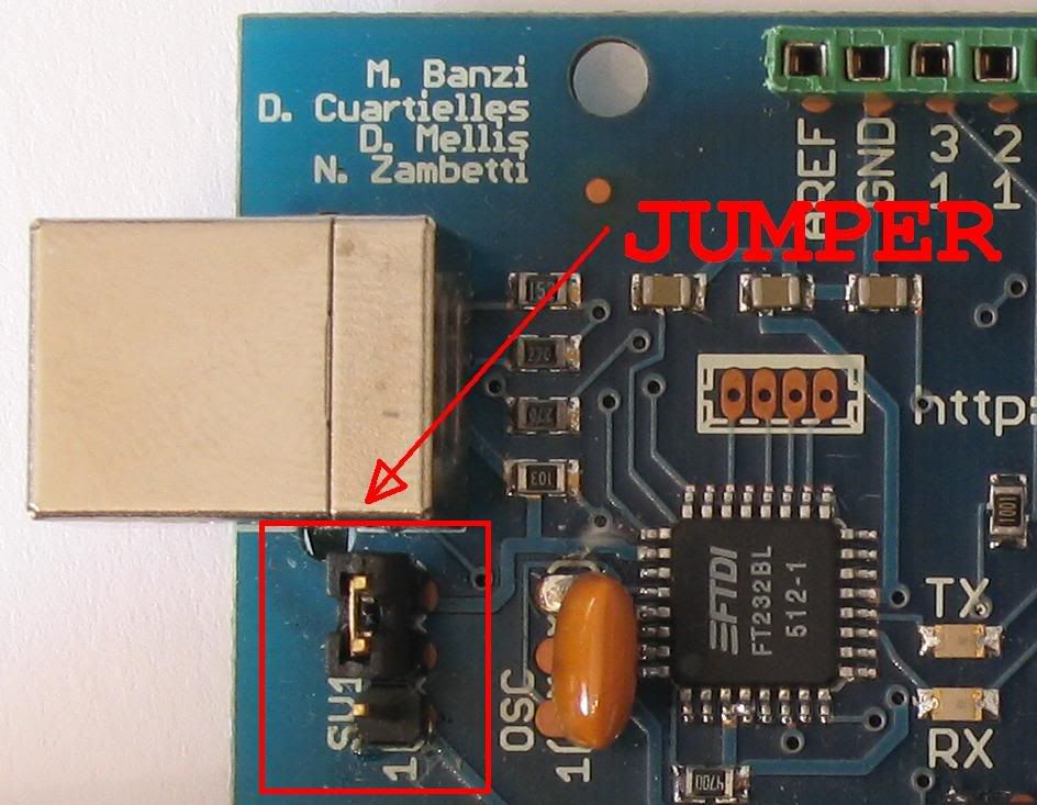
used to connect the Arduino board with PC , transfer the program or to communicate during the execution of programs. Jumper
supply:
This jumper is the latest models.
Together USB connector is a jumper to select that if the power is provided by the PC itself through USB or take power from the power connector.
The picture shows the position of jumper to power the board from the USB :

reset button:
is the small button that is in the center of the plate, when compiling the code with the program, press and you will immediately go to the arduino board.

We will analyze the latest version of arduino the USB controlled.
has power inputs:
can be powered by a power supply between 6 and 25V to through the connector with the following polarity:
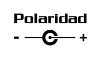
No is necessary to feed circuit while the USB is attached.
Power outlets:
have several power outlets to supply power to auxiliary circuits such as LEDs, buttons etc. These are marked with their value (5V, 3.3 V and GND
)
Analog inputs:
is the 6-pin marked "Analogic in " we can enter values analogue of between 0v and 5v.
Input / Output digital:
14 pin marked as "digital," these pin can function as digital inputs or outputs, depending on program content. Since 0v or 5v outputs provide, ie a 0 or a logic 1.
When functioning as inputs is exactly the same as 1 take a value of 5v and 0v logic 0 when they are at the entrance.
Port USB :
used to connect the Arduino board with PC , transfer the program or to communicate during the execution of programs. Jumper
supply:
This jumper is the latest models.
Together USB connector is a jumper to select that if the power is provided by the PC itself through USB or take power from the power connector.
The picture shows the position of jumper to power the board from the USB :
reset button:
is the small button that is in the center of the plate, when compiling the code with the program, press and you will immediately go to the arduino board.
Birthday Musics Arabic
Arduino is a system controlled by a microcontroller, a plate on which have the same inputs and outputs, and a port to communicate with the computer.
is totally free, including software, ie we can mount the plate and get the program compiler from HERE.
This program is similar to a C compiler, so you have to have basic knowledge in this language.
Some of the reference pages are:
official Web Arduino.
Freeduino (in English).
40 projects (English).
The official website can find the designs of the plates for several versions of Arduino.
Although we can also find assembled or in kit form in ebay.

Monday, January 12, 2009
Mouse Modelmoakuo Does Not Scrll Right
! New secion! Section
Now available a new section is the section "download area" where you will find utilities, tutorials and programs for each subject or branch of electronics.
addition to some exercises and work assignments
Be patient and gradually increasing against files in each of the sections.
 University IES laboral.Albacete
Analogue electronics.
digital electronics.
Computer and programming. 
Now available a new section is the section "download area" where you will find utilities, tutorials and programs for each subject or branch of electronics.
addition to some exercises and work assignments
Be patient and gradually increasing against files in each of the sections.
 University IES laboral.Albacete
 Analogue electronics.
digital electronics.
Computer and programming.
Subscribe to:
Posts (Atom)